This is part of a series of posts about building an Orone Mini, a Maple Mini clone that is designed to be easier to build by hobbyists. It primarily uses surface mount technology, and there are a couple of fine-pitch (0.5mm) devices, so it’s not easy to solder by hand. This means I need to use a solder stencil.
I want to make my own stencils, since I want faster turnaround time. But how to do it? Adafruit has a great tutorial on making SMT stencils, but the final output step uses a laser cutter. I don’t want to buy a laser cutter, since they’re in the thousands of dollars – making my own laser stencil cutter is cool, but right now I don’t have the time for it. Making aluminum stencils also sounds cool but I don’t want to mess around with muriatic acid and other chemicals each time I want to make one.
On Hack A Day I heard about using a vinyl cutter to cut stencils which linked to Peter Monta’s wonderful program gerber2graphtec.
This is a command line program that takes gerber files output by an EDA program (in my case, Eagle) and turns them into something that the inexpensive Silhoutte Cameo stencil cutter can understand. You can get more info on Peter Monta’s SMT Stencil Cutting blog post, or this one at DM Studios on stencil cutting.
Here’s what worked for me:
- Graphtec Silhouette Cameo stencil cutter bundle – $270 as of the writing of this blog post, much less expensive than a laser cutter.
- 3M PP2500 overhead transparency film
- Avery 5353 full-sheet labels
- Citrasolv citrus solvent
- Dental pick
- Wide-field microscope (about $180; I also use it for SMT joint inspection) or magnifying glass
This is pretty much exactly as Peter Monta explains in his SMT stencil cutting blog post. I tried some of the other ways he thought might work – using the cutting mat instead of the full sheet label, or using spray-on removable adhesive. But these weren’t as successful – I think the Avery labels stick well and keep the plastic film from bending while the cutting is going on.
I’m on Mac OS X using Homebrew (rather than the MacPorts that Monta uses). Here’s the steps I went through.:
- Install the non-Python dependencies for gerber2graphtec:
$ brew update
$ brew install gerbv pstoedit libusb
- Make a Python virtual environment to hold the Python dependencies
- If you don’t have Python and pip, install them. (Using brew to install Python installs pip.)
$ brew install python
- Install virtualenvwrapper and make a Python virtualenv to keep the Python dependencies separate from your global libraries (this step is optional):
$ pip install virtualenvwrapper
$ mkvirtualenv eda
- Install the Python dependencies:
$ pip install libusb1
- Clone the gerber2graphtec project
$ git clone https://github.com/pmonta/gerber2graphtec.git
$ cd gerber2graphtec
- Use an EDA tools to produce the solder stencil layer (tcream layer in Eagle) gerber files as in the Adafruit SMT stencil tutorial. I use a 1-mil shrink – that is, I shrink all the pads by 1 mil so the solder paste doesn’t overflow too much. This is a compromise – I’d really like to shrink by 3 or 4 mils, but the stencil cutter doesn’t produce perfect holes if I shrink the fine-pitch pads that much, and the solder paste I’m using (lead-free Kester NXP) doesn’t go through the small holes that well. 1-mil shrink seems to work fine.
-
Check the gerber2graphtec options to get ready to convert your gerber to something the Cameo will understand:
$ ./gerber2graphtec
usage: gerber2graphtec [options] paste.gbr >/dev/usb/lp0

options:
  --offset x,y        translate to device coordinates x,y (inches)
  --border bx,by      leave a border around the bounding box of the gerber file
  --matrix a,b,c,d    transform coordinates by [a b;c d]
  --speed s[,s2[,s3]] use speed s in device units; s2,s3 for multiple passes
  --force f[,f2[,f3]] use force f in device units; f2,f3 for multiple passes
  --cut_mode [0|1]    0 for highest accuracy (fine pitch), 1 for highest speed

defaults:
  --offset 4.0,0.5  suitable for letter size (portrait) on the Cameo, fed as "media" not "mat"
  --border 1,1      1-inch border in x and y around gerber bounding box
  --matrix 1,0,0,1  identity linear transform for scale and skew calibration
  --speed 2,2       use two passes, speed 2 in each pass
  --force 8,30      use force 8 for first pass, force 30 for second pass
  --cut_mode 0      highest accuracy
- Process the tcream gerber file to make a file that can be sent to the Silhouette Cameo (.gtec file). These settings are for a 0.5 inch bounding box around the board outline; gerber2graphtec calculates the border from the bounding box of the stencil, which may not be the edge of the board. I’m adding an offset so the stencil is cut into the right edge of the sheet.
$ gerber2graphtec --speed 1,1,1 --force 8,15,29 --cut_mode 0 --offset 0.5,5.5 --border 0.645,0.6667 Orone-mini-S8H-v0r001.tcream.ger > Orone-mini-S8H-v0r001.tcream.gtec
I’m using 3 passes with increasing force – with three passes I can get almost perfect cut-outs of the fine-pitch pads.
- Attach a full sheet label to the transparent overhead film – make sure there are no bubbles and the film is firmly attached
- Set the 45 degree cutting blade to setting 1. (With the Avery 5353 labels stuck to the PP2500 film, I found blade length setting 1 perfect using 3 passes, first pass at force 8, second at force 15, third at force 29.)
- Load the film+label as media (without the cutting mat)
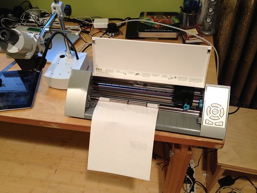
- Send the gtec file to the Cameo cutter:
$ file2graphtec Orone-mini-S8H-v0r001.tcream.gtec
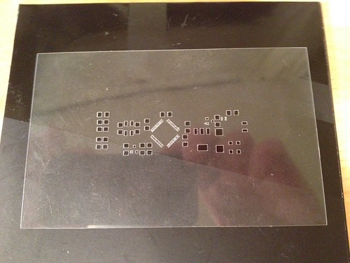
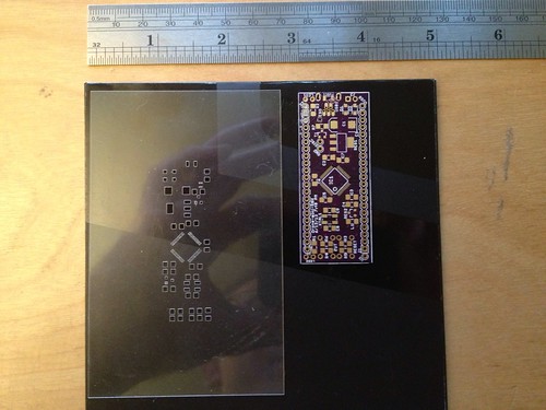
- Unload the media, peel off the stencil:
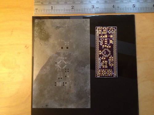
- Remove paper from stencil by running under water and rubbing – this picture shows the stencil with the adhesive gunk still on it:
- Remove adhesive using Citrasolv and sponge
- Rinse with clean water and dry
- Examine under microscope or magnifying glass – remove chads that are still stuck using the dental pick
- You are done!
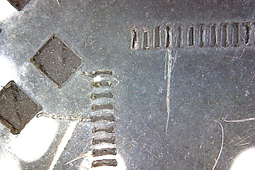
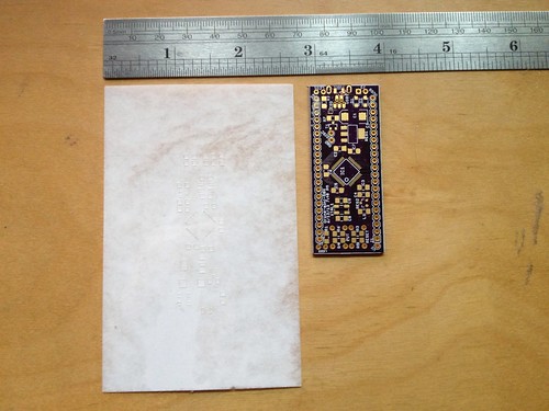
Using the 3-pass progressively harder pressure, on a fresh sheet with no other stencils cut out of it, I can get almost perfectly square holes even on the fine-pitch pads. The picture above shows a 2-pass run I did on sheet that had other stencils cut out of it. I think the fine-pitch TQFP pads are distorted on this one because the Orone Mini has the STM32 fine-pitch TQFP part laid out on a diagonal – when I cut the test coupon that had fine pitch pads layed out straight, the fine-pitch pads came out almost perfectly:
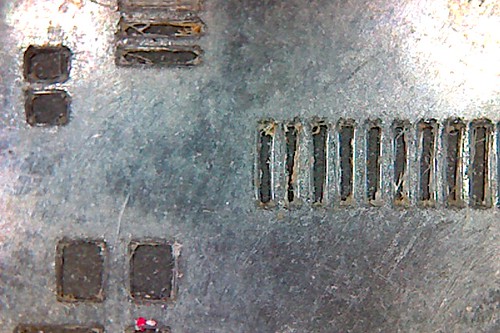
When I went to the 3-pass using a fresh sheet, my fine-pitch diagonal pads look like this too. Success!
John
Great write up Adam. If you want an alternative solution, you should check out OSH Stencils. They make cheap low cost stencils that are professionally laser cut starting at just $5. I used to make my own too but I ended up switching because the price was so low it didn’t make sense dealing with the imperfections of cutting them myself. Just thought I’d share that, happy building!